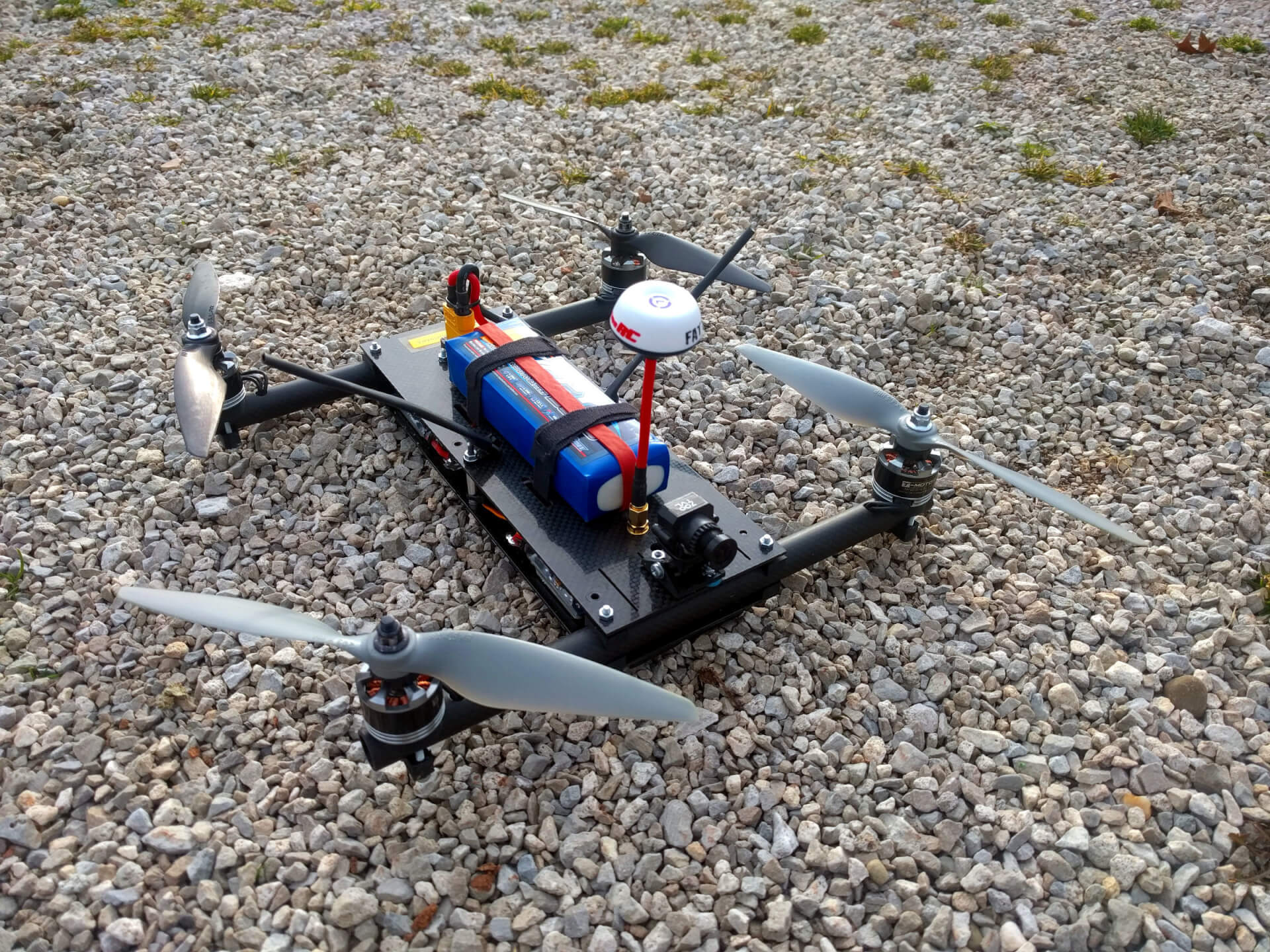
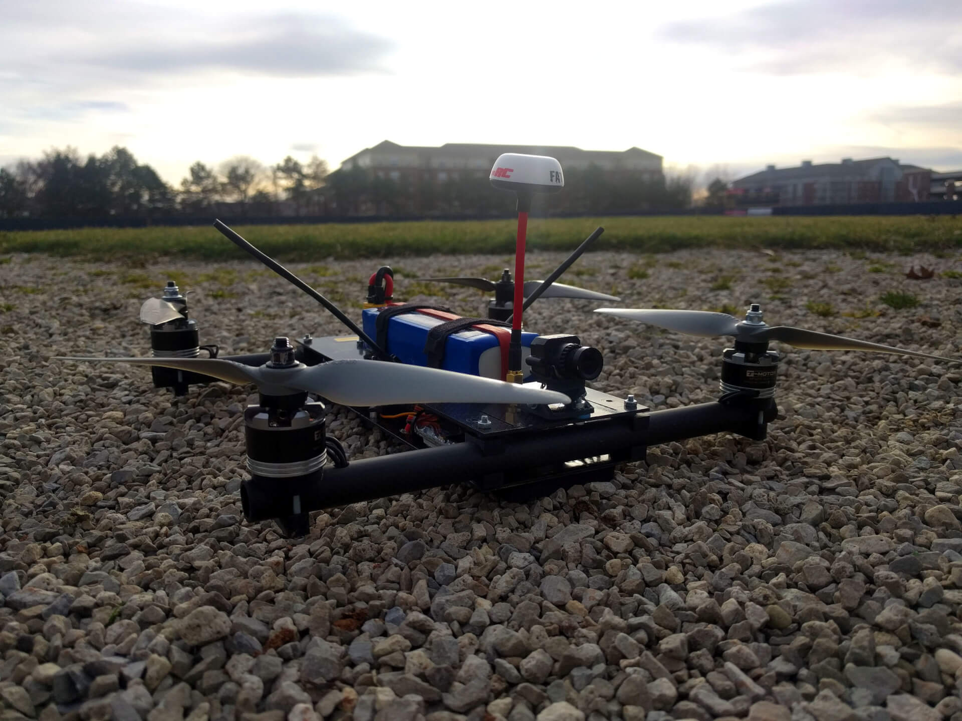
350mm H Quadcopter
A 350mm H-style quadcopter that I designed to be more durable and reliable. Some of the components I reused from the X-quad, but on a lot of things, like the carbon fiber frame, I started fresh.
In early 2017, I made some revisions to the design. The frame was redesigned to increase its ability to withstand a crash and to reduce weight. The entire power system was replaced with higher quality components, so the flight times have improved significantly.
Everything related to this build can be found on GitHub, including drawings and schematics.
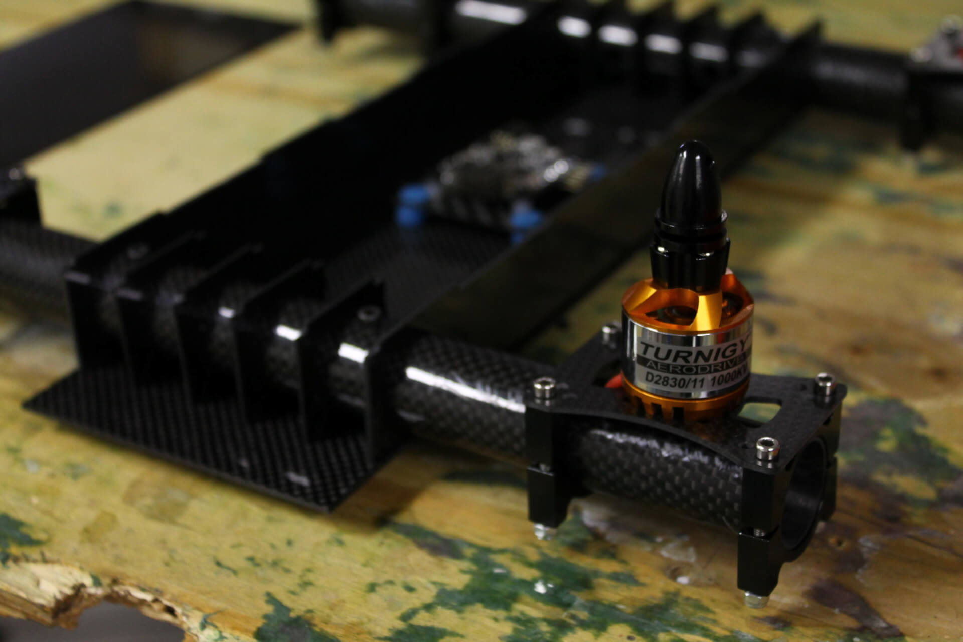
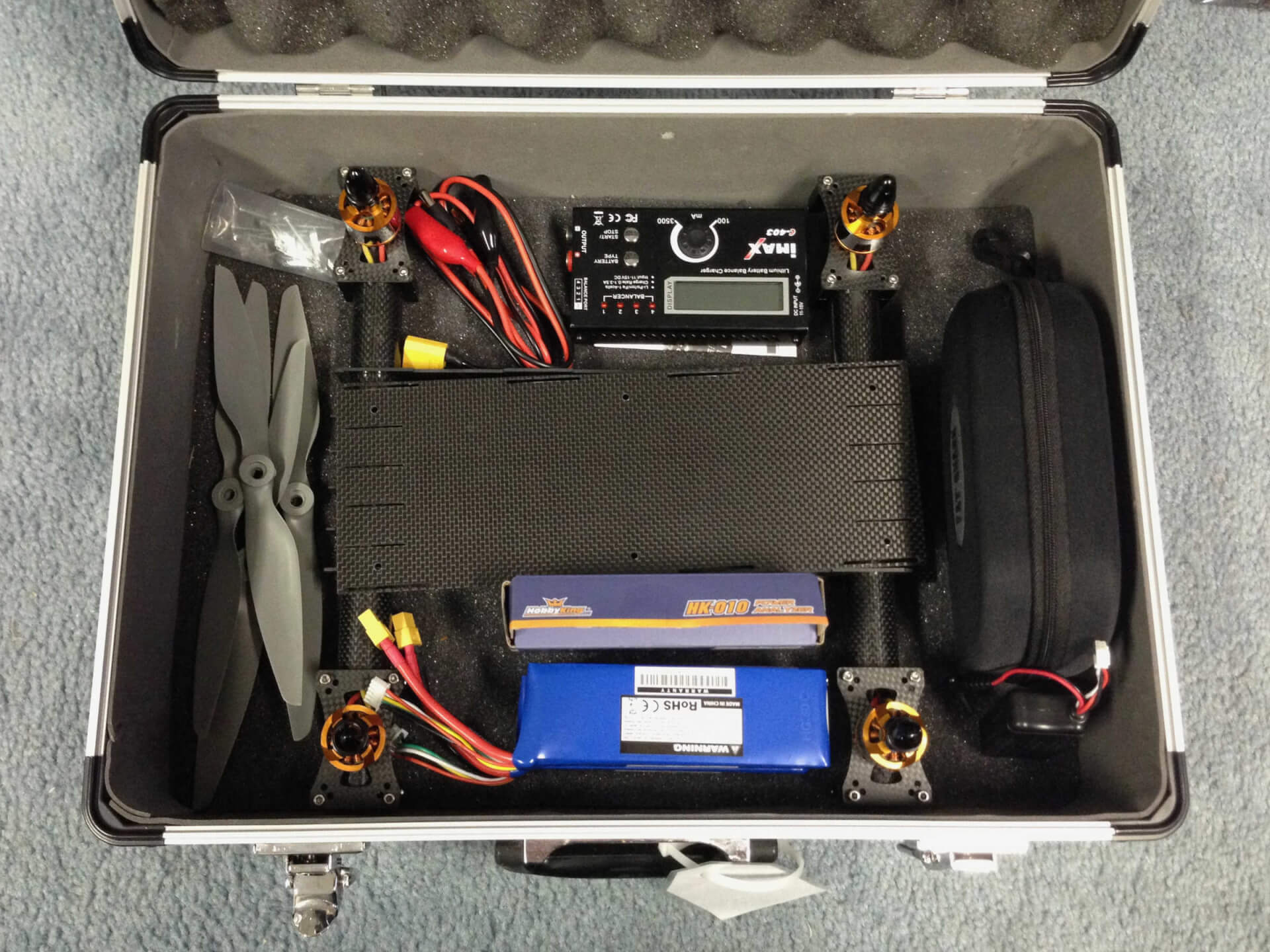
Photos of the original frame design:
Specs
- Frame: Custom 350mm; 16mm carbon fiber tubes, 1.5mm carbon fiber plate, 3D printed motor mounts
- PDB: Custom 120 A with power switch, current sensor, and filtered VTX power
- Motors: Tiger Motor MT2208-18 1100kv
- ESCs: Hobbyking Blueseries 30A running BLHeli
- Props: APC Multirotor 8x4.5
- Battery: Lumenier 3300mAh 4S 35C Lipo
- Flight Controller: Naze32 fully-featured running Cleanflight
- Reciever: OrangeRX R617XL 6ch 2.4GHz
- OSD: Micro MinimOSD w/ KV Team Mod
- FPV Camera: RunCam Owl Plus 700TVL
- FPV Transmitter: FatShark 5.8GHz 250mW w/ ImmersionRC LHCP SpiroNet antenna
Specs (Original Design)
- Frame: Custom 350mm; 25mm carbon fiber tubes, 1.5mm carbon fiber plate
- Motors: Turnigy Aerodrive D2830-11 1000kv
- ESCs: Turnigy Multistar 30A w/ SBEC
- Props: APC Multirotor 9x4.5
- Battery: Zippy Flightmax 3000mAh 4S 20C Lipo
- Flight Controller: Naze32 fully-featured running Cleanflight
- Receiver: OrangeRX R615x 6ch 2.4GHz
- Telemetry: cheap clone of 3DR Telemetry Module 915mHz
- FPV Camera: FatShark 700TVL CMOS
- FPV Transmitter: FatShark 5.8GHz 250mW w/ ImmersionRC LHCP SpiroNet antenna
Updated Frame Design
It’s been a really, really long time since I’ve posted anything here. I’ve been extremely busy with school stuff and I haven’t had the time or motivation to keep things documented. Regardless, a lot of progress has been made since the beginning of 2016. The second version of my quadcopter frame saw its first flight and first crash, which led me to realize a few of the major issues with the design and cause me to get to work on a revision.
The Crash
It turns out the main reason for the crash was because the default PID values in Cleanflight are set really high and are meant for 250-sized quads. Too high of a P-gain caused oscillations which made the quad unstable, resulting in a flip and it flying straight into the ground. ALWAYS check your PID values before the maiden flight! If you’re building a quad larger than 250, it’s probably a good idea to lower those values by half or something. I found that it’s better to have low values and be under-tuned rather than be over-tuned and lose control.
The crash also revealed that the motor mounts were a weak point in the design. The el-cheapo mounts I bought off Amazon couldn’t handle the force of the motors when they hit the ground, and the mounting screws ripped right through the 1mm carbon fiber plate that the motors were mounted to. The wall thickness of the tubes was also a little on the thin side, as I was able to crack one tube when I tightened the motor mounts.
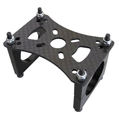
I was aware at this point that I needed to come up with a better way to attach the motors, and while I was at it, I should also address other minor issues that I discovered. The next revision of the frame needed stronger motor mounts, stronger tubes, improved rigidity of the center section, and reduced weight.
Power System Changes
A few days after the crash, I had temporarily repaired the motor mount and was eager to get out and attempt another flight. During some bench testing (without props, of course!) I noticed that one of the motors would not spin properly, and upon a closer look, I realized that one of my motors had shorted windings. I’m almost certain that the short was not caused by the motor mounting screws, and since the motors were essentially new, I assumed the failure was related to build quality. The Turnigy motors I had were fairly low quality and had a really stiff coggy feel when rotated. They were by no means known for efficiency or longevitiy.
Rather than buy a replacement motor, I elected to upgrade the power system with new motors and props. After a decent amount of time in eCalc and looking at motor reviews, I decided on something that was a big step up from what I had: the T-Motor MT2208-18 1100kv. While roughly the same size and kv, these motors are known for quality, are significantly more efficient, and had a lower weight. I am extremely impressed by the build quality and they have a nice smooth feel when rotated by hand.
After selecting a motor, I went with APC 8x4.5 props which are one inch smaller than what I previously had. With a 350 sized frame, now my quad should be able to fit in its case with the props on. I was able to cross reference the prop selection table provided by T-Motor with what eCalc said, so I am confident that I’ll have a system that gets good flight times while not sacrificing performance.
While I was at it, I also picked up counter-clockwise prop adapters for two of the motors as well as matching nylon locknuts.
Frame Design Changes
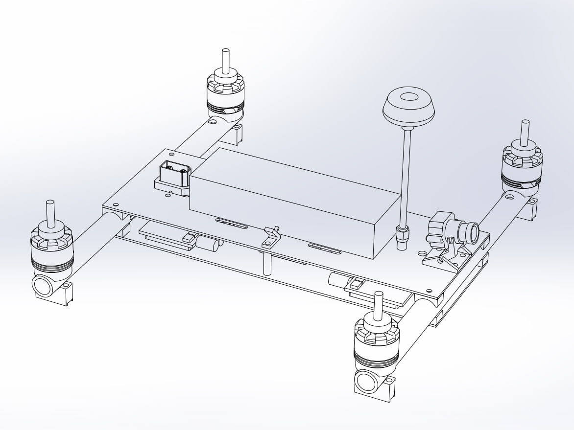
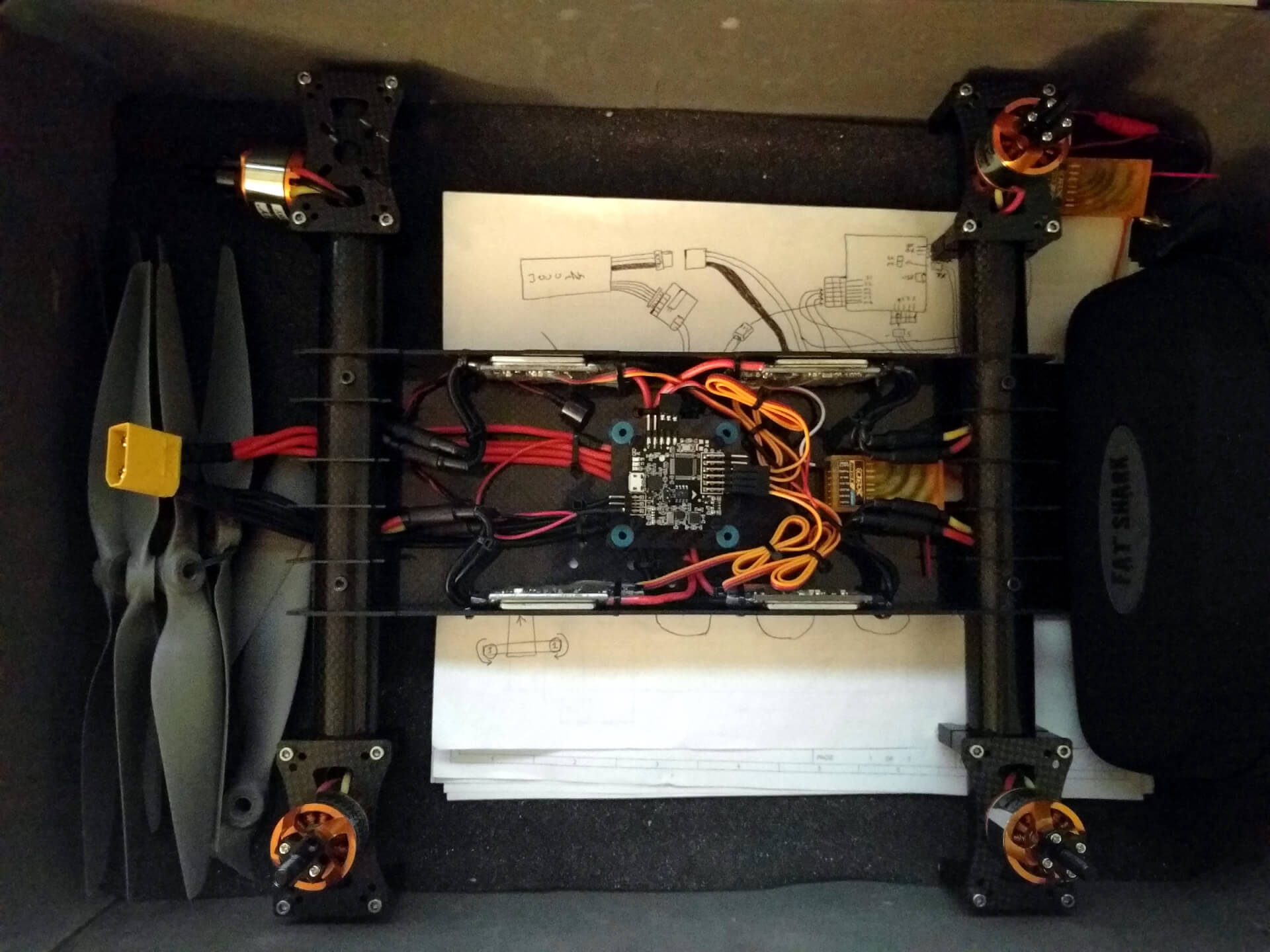
The two main goals for the updated frame were strength and weight reduction. I reduced the OD of the tubes from 25mm to 16mm and increased the wall thickness from 1mm to 2mm. The previous build had a big bundle of silicone wire to get power to the ESCs, so in order to save weight, I elected to replace the bottom carbon fiber plate with a power distribution board. This would allow me to clean up the wiring as well as add some cool features that I’ve seen on other PDBs, such as a current sensor. The old frame had vertical carbon fiber pieces that pressed into slots in the bottom and top plates, which made the frame a pain to assemble. I figured that they don’t provide enough value to justify their weight, so I got rid of them.
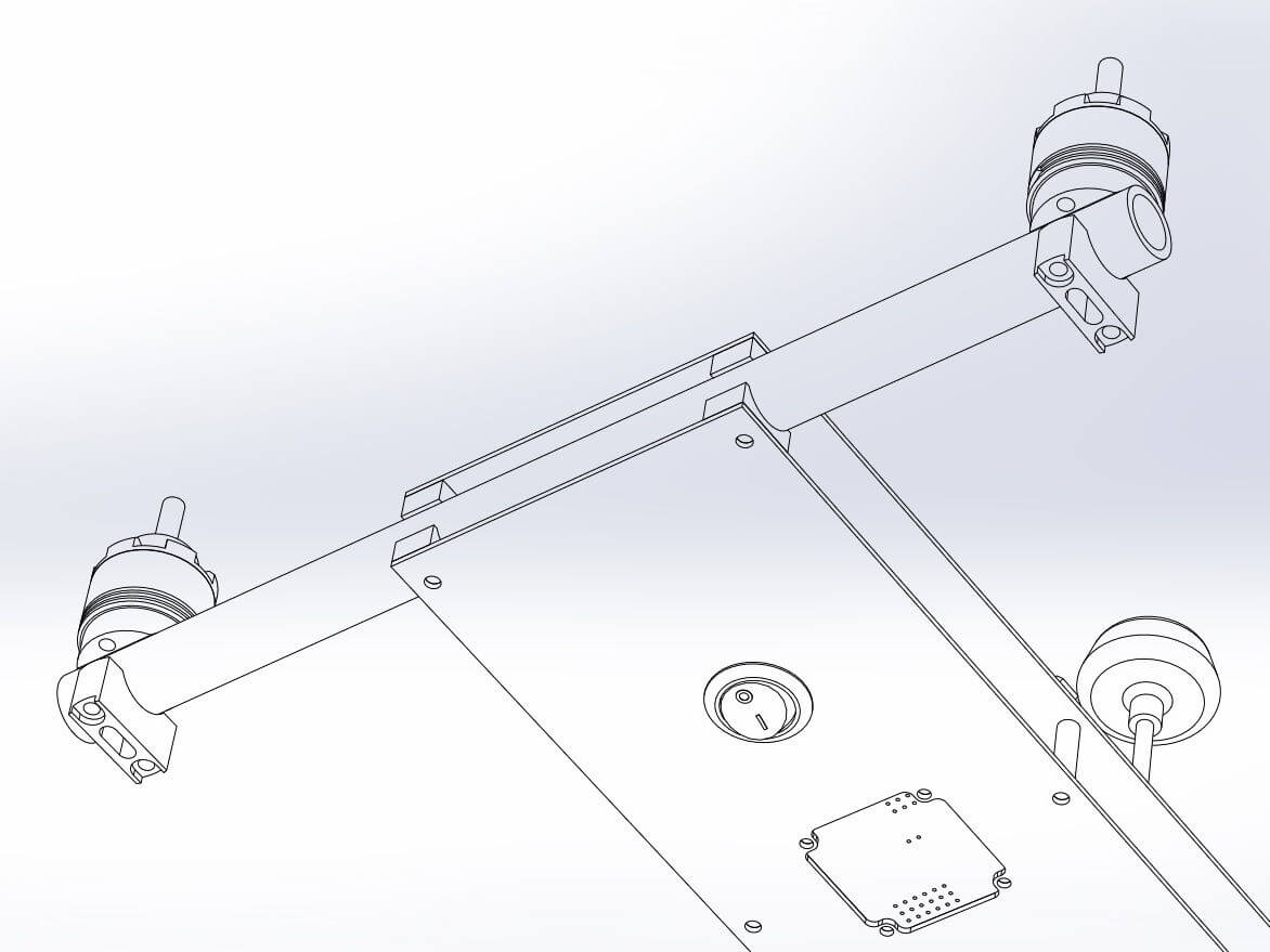
I also made a few other changes that made the design a little cleaner. I designed a motor mount that is no bigger than the motor itself and only includes hardware that screws directly into the base of the motor. Rather than hang an XT90 pigtail out the back of the quad, I designed a panel mount bracket so that the connector could be mounted directly to the top plate. This also gives me something to pull against which makes it easier to unplug the battery. I bought a short U.FL to SMA pigtail so that the FPV transmitter antenna could mount directly to the top plate.
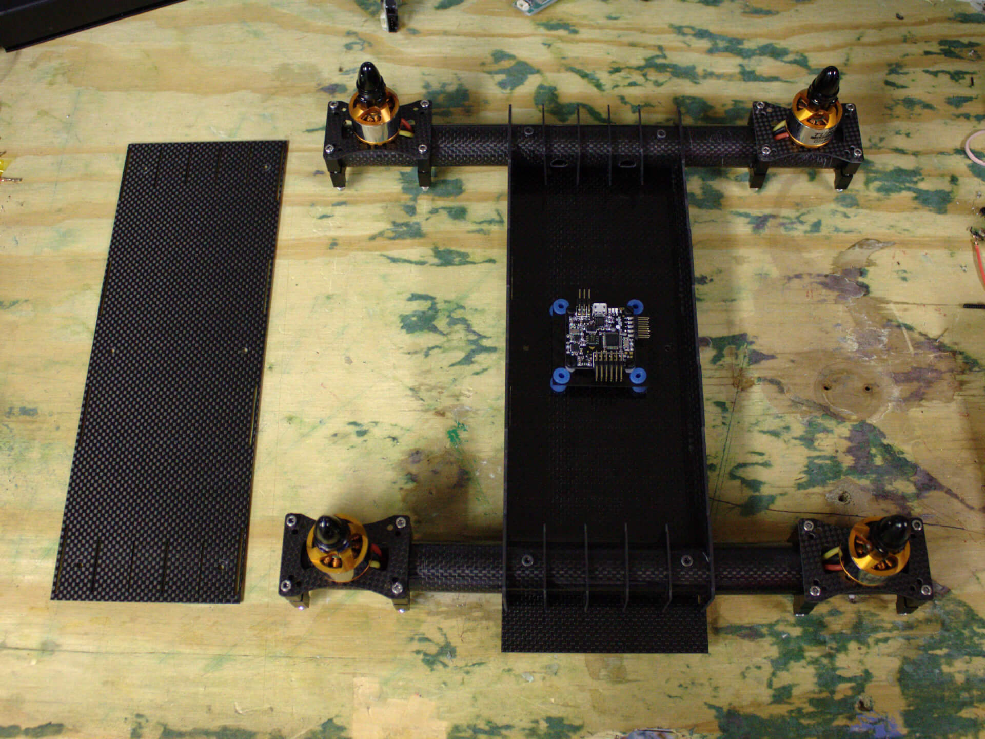
Custom 350 H-Quad Frame
I’ve spent the last week designing and building a new frame as I refurbish my quadcopter. It has been a lot of work, but I finally have something that is lightweight, durable, and looks awesome.
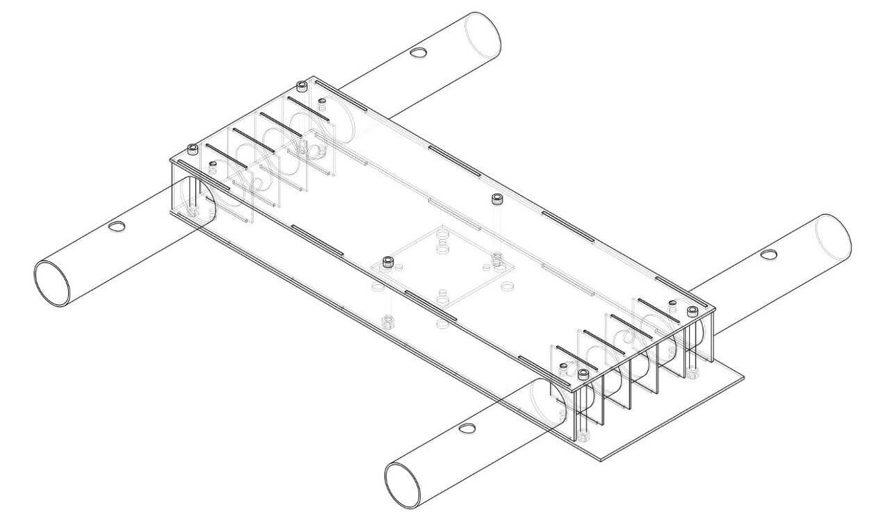
Before I got to work drawing up the design in FreeCAD, I had to decide on a few things. First and foremost, I had to decide between a X, +, or H configuration for the motors, each configuration having its pros and cons. For my previous frame, I had gone with the X configuration simply because it was a popular and very standard design. However, as I started mounting the various components, I realized that it doesn’t leave much room in the center to put everything. The + configuration isn’t much better, so for this frame I went with the H configuration instead. This gets me a large platform to mount the electronics.
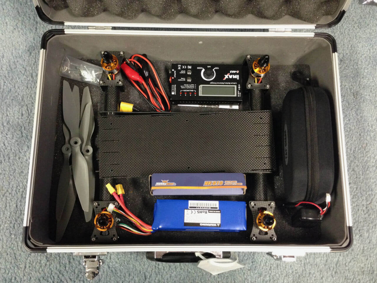
The new frame is slightly smaller than the old one at about 350mm between motors diagonally. The smaller size allows me to reuse an old aluminum hard case I had laying around to carry the quadcopter and all the stuff that goes with it. I could have instead went with 250mm frame and build a mini race quad, but the slightly larger size makes the quad more stable and allows me to fit larger propellers in order to maximize battery life.
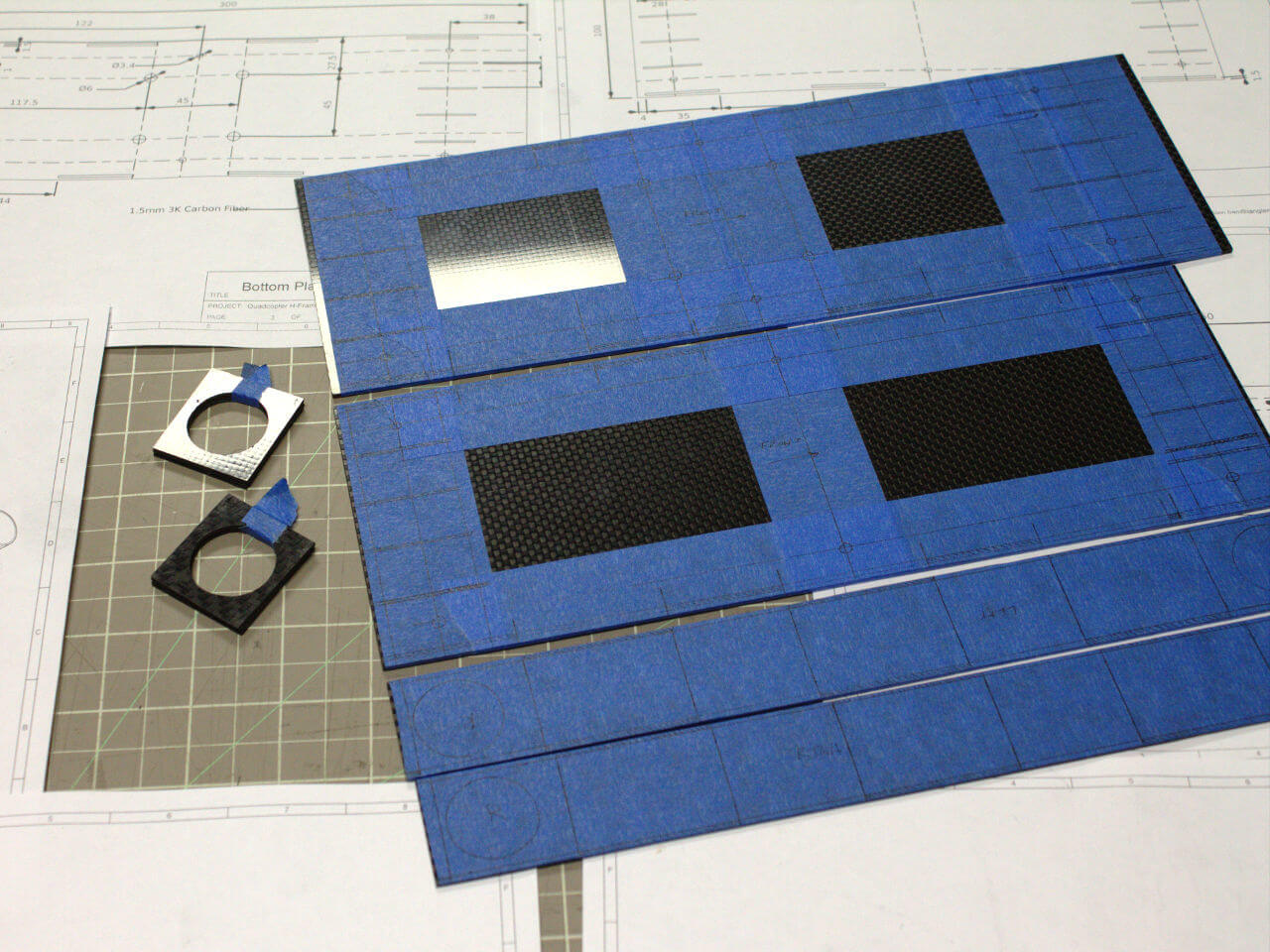
The entire frame is constructed out of 1mm and 1.5mm thick 3K carbon fiber, including the beams. This allows the frame to be extremely lightweight but at the same time be quite durable and stiff. I discovered that carbon fiber can be bought on eBay and Amazon for fairly cheap. It’s comes direct from China and, surprisingly, the quality is really good. The design is loosely based off the FT VersaCopter, especially the beam supports.
It took me a few days to fabricate the carbon fiber parts, as I hand-cut them using a Dremel, bench grinder, and drill. It was extremely tedious, and access to a CNC router or laser cutter would have helped a lot, but I am happy that the parts came out pretty close to the original dimensions. In addition, I had to do a lot of precise cutting in order to make sure everything fit together perfectly. If I were to build another frame, it would probably benefit from larger clearances between parts.
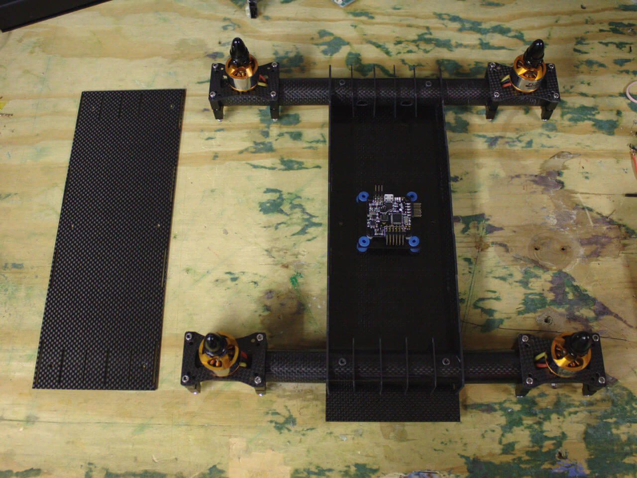
After all that work, I’m left with a very cool looking frame that has plenty of room to mount components, which should result in a very clean quadcopter with very good cable management.