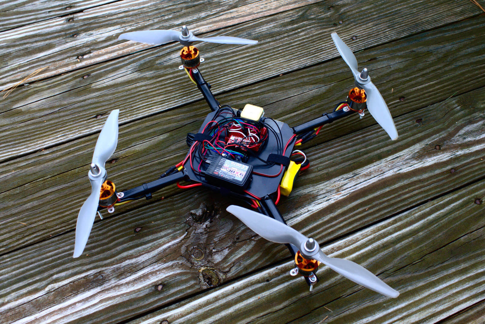
400mm X Quadcopter
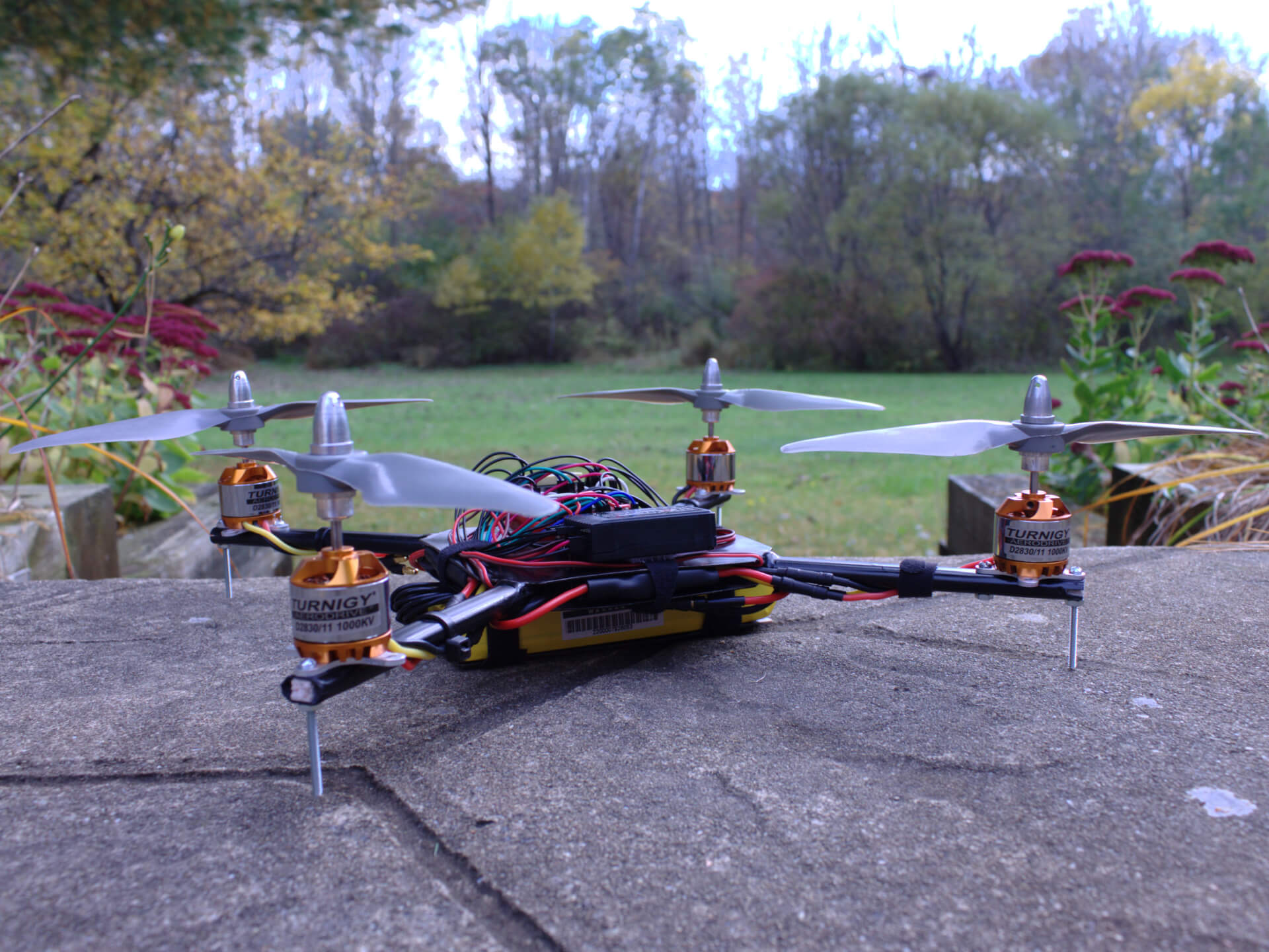
A 400mm X-style quadcopter that I built on a tight budget with no prior experience with quadcopters or RC aircraft.
Many naive design choices were made, and while it flew, it was not durable and did not perform well. It met its fate after suffering a hard crash which caused the frame to completely disintegrate.
Specs
Note: Please do not build a quadcopter using this spec list. It doesn’t fly well.
- Frame: Custom 400mm; Made from plastic tubing and fiberglass
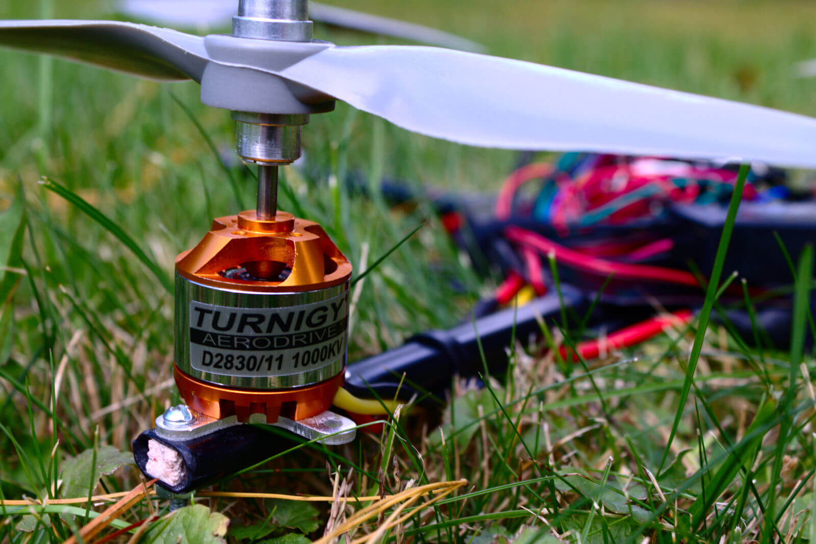
- Motors: Turnigy Aerodrive D2830-11 1000kv
- ESCs: Turnigy Multistar 30A w/ SBEC
- Props: Cheap clone of APC Electric 8x4
- Battery: Zippy Compact 4000mAh 3S 25C LiPo
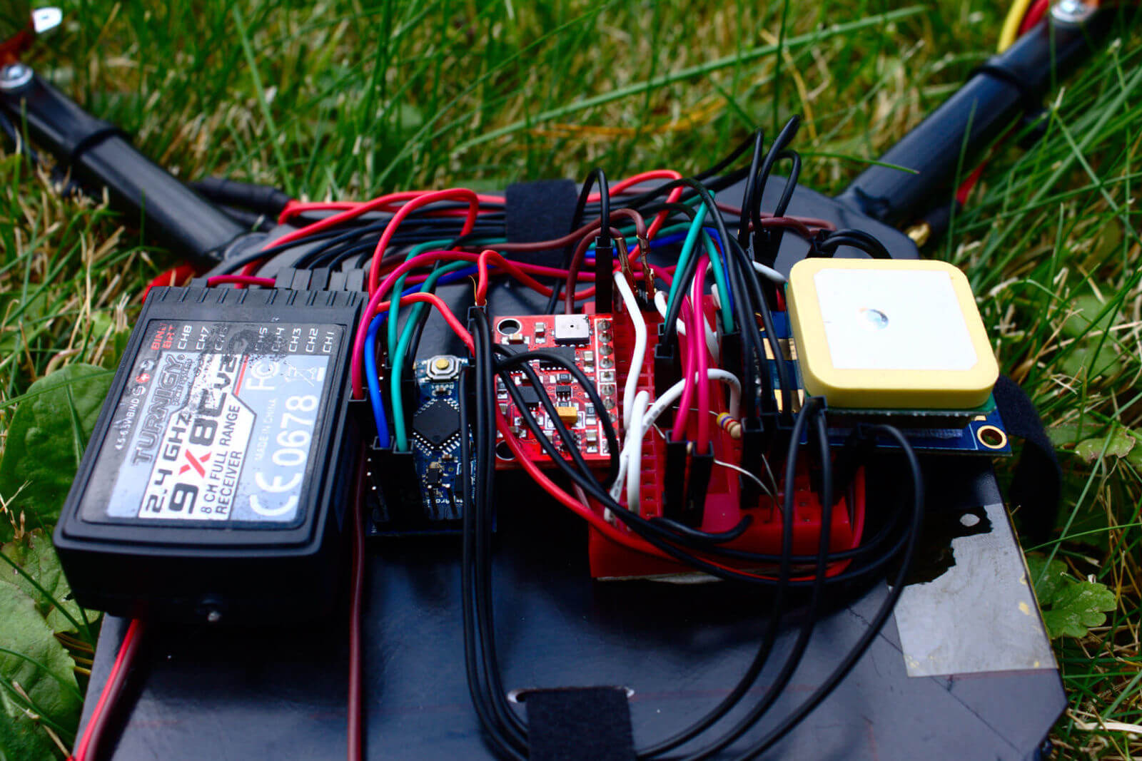
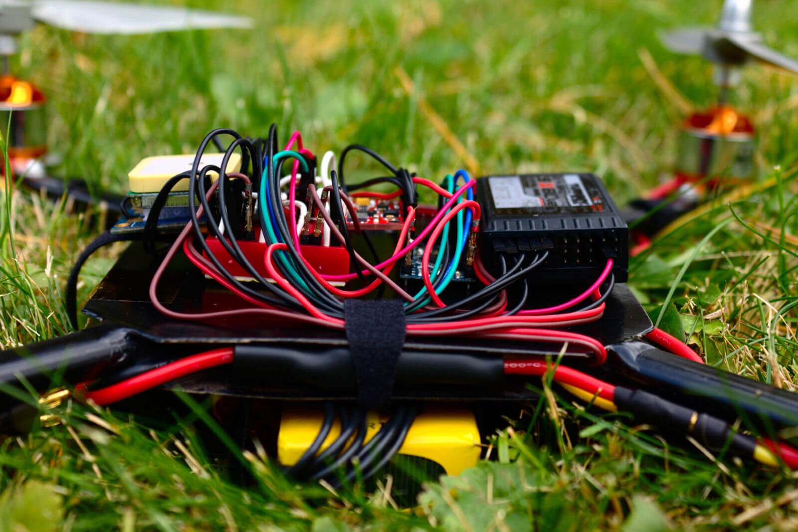
- Flight Controller: Arduino Pro Mini running Multiwii w/ GY-80 IMU
- Receiver: Turnigy 9X8C v2 8ch 2.4GHz
- Telemetry: Cheap clone of 3DR Telemetry Module 915mHz
Quadcopter Status Update
It’s been quite a long time since I posted anything about my quadcopter and a lot has happened. Which includes me crashing it and destroying the frame.
The original design, while it did accomplish what I had set out to do, had major issues with design and execution that I am just now beginning to realize. They say you get what you pay for, and in my case, building a quadcopter on a tiny budget meant that it would perform quite poorly. The frame was probably the weakest link. It was a good idea in theory, but I underestimated how brittle the plastic frame tubes actually were. With no integrity, all it took was one crash to completely obliterate it into a million little pieces.
I could’ve simply built a new frame in the next few weeks using some scrap wood, but the crash caused me to rethink some of the design decisions I’d made and replace some things that I knew were bound to fail in the near future.
It turns out that the IMU was also at fault for the crash. To keep costs down, I opted to go with a cheap (~$10) IMU module on eBay. While many people say these modules work and are good enough for quadcopter use, I neglected to look at the rated voltage. The core of my flight controller is an Arduino Pro Mini running at 5 V. So, I powered the IMU module with the 5 V output from the Arduino, assuming that since it was sold as “Arduino compatible” it would work just fine. I failed to notice that even though the module had an on-board regulator and could accept 5 V, the I2C pins were not rated for 5 V and did not include a level shifter. Oops.
My guess is that after no longer than 20 seconds in the air, I fried the IMU module and the quad fell out of the sky, smashing into the ground and destroying the frame.
Now that I’m off for winter break and have a bunch more free time, I’ll focus on building a new frame, replacing the flight controller with something more reliable, and redoing motor and prop calculations in order to boost efficiency and flight time. I’m thinking about switching to a Naze32, as I was unaware until recently how inexpensive they were and that they run baseflight, a fork of Multiwii. I’ll try to post more updates in the next few weeks as I refurbish my quad.
Flashing ESCs with Simonk
As I have begun to learn more and more about this whole quadcopter thing, I’ve heard many people recommend replacing the stock firmware that comes with ESCs with a custom firmware, Simonk, that is specifically tuned for multicopters.
The SimonK firmware, named after the creator who is known as SimonK on the forums, provides smoother throttle response and should give better all around performance when used in a multicopter configuration. Supposedly it can also increase the refresh rate and has less bugs than the stock firmware.
So I decided to flash my four Turnigy Multistar 30 amp ESCs which are part of my quadcopter.
If you’ve ever used an Arduino before, flashing the firmware of an ESC isn’t much harder than loading a program. Most ESCs are powered by an AVR microcontroller, which makes it a walk in the park to upgrade the firmware. All you need to do is hook your ESC up to a programmer—which can be an AVR programmer, an Arduino, a Bus Pirate, etc.—and run avrdude to erase the chip and flash the new firmware.
Disclaimer: When flashing ESCs, there is the potential to ruin the ESC and turn in into a paperweight. Make sure that the version of SimonK being flashed has been verified as compatible with the specific ESC model, although there is no guarentee of functionality. Also note that the factory firmware on the ESC will be overwritten and unrecoverable.
Hooking It Up
To get started, I removed the green heat shrink to expose the board. Take care not to damage any of the components under the heat shrink when cutting the heat shrink.
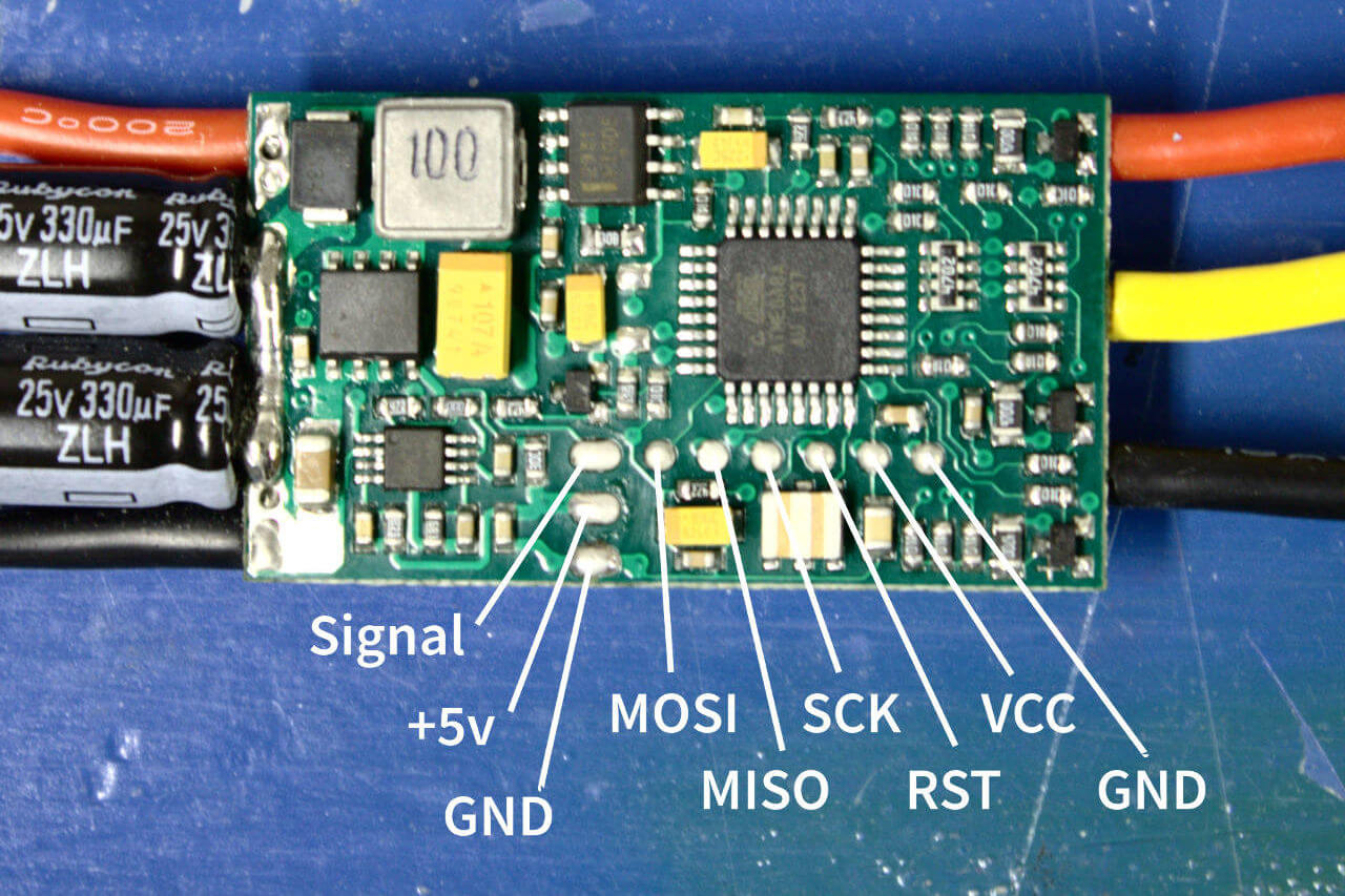
There are six pads for in system programming near the microcontroller near where the sigal wires connect to the board. In my case, I had to desolder those wires in order to get access to the pads.
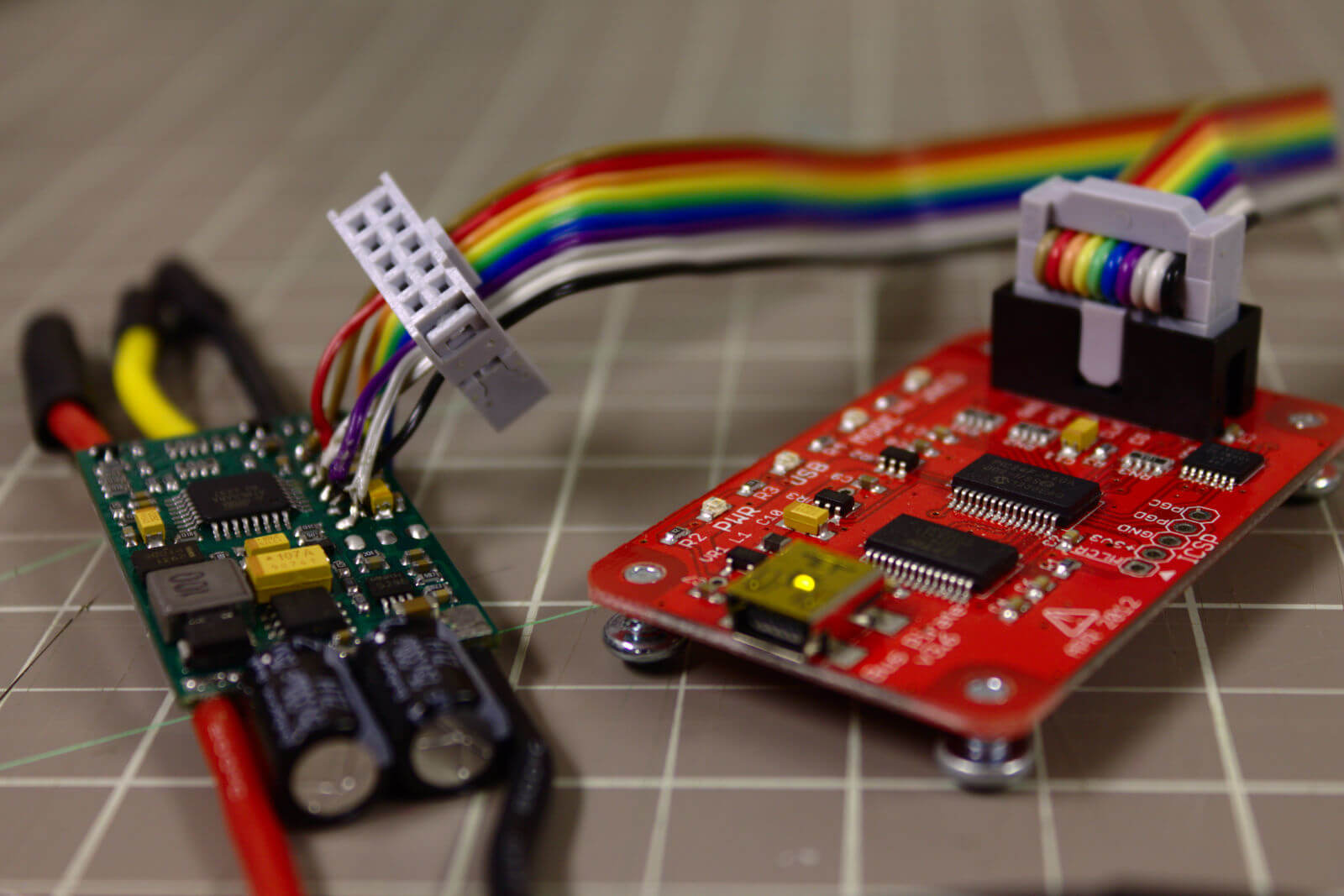
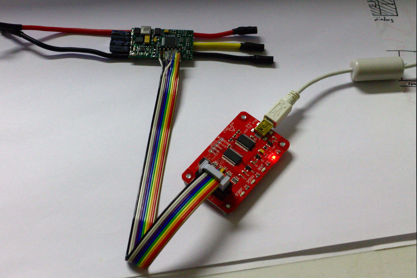
I’m using my Bus Pirate to flash the firmware. I had to remove one end of the ribbon cable and move it inward in order to be able to solder each wire to each individual pad. It can be a little tricky to solder those tiny wires and still maintain the correct order.
If you plan on flashing many ESCs, I might be a good idea to get a clothespin a make a programming mount to make it easier to switch between boards. I decided to solder the wires directly to the pads. With only four boards, it doesn’t take that much time.
For the Bus Pirate the connections are as follows:
- Bus Pirate MOSI → MOSI
- Bus Pirate MISO → MISO
- Bus Pirate CLK → SCK
- Bis Pirate CS → RST
- Bus Pirate 5v or 3v → VCC
- Bus Pirate GND → GND
The connections might be different depending on the programmer being used.
Flashing the Firmware
Once everything was ready to go, I had to figure out which version of Simonk would work with Turnigy Multistar ESCs. Based off of this forum post, it appears that the kda version is compatible with Turnigy Multistar ESCs up to 30 amps. I downloaded the latest version of Simonk, which include the hex files for each specific version.
Now it’s time to use avrdude to actually do the flashing. I plugged in my Bus Pirate and opened a terminal.
If you haven’t installed avrdude, the easist way to get it is probably through installing the Arduino GUI. There are also a few avrdude packages available for major Linux distros.
As a precaution, I started by using avrdude to read the factory firmware from the ESC and write it to a file. In the event that something goes wrong, I should be able to use this to restore the factory firmware. Otherwise, it would be overwritten by SimonK and lost forever.
$ avrdude -c buspirate -P /dev/ttyUSB0 -p m8 -U flash:r:factory.hex
Make sure to set the appropriate options for avrdude, including programmer, chip type, and com port.
It’s time to flash Simonk. Make sure kda.hex is in the same directory as avrdude is being run.
$ avrdude -c buspirate -P /dev/ttyUSB0 -p m8 -U flash:w:kda.hex
Flashing the firmware should look something like this, where avrdude write the file and then reads it back to ensure that it was written correctly:
Attempting to initiate BusPirate binary mode...
avrdude: AVR device initialized and ready to accept instructions

Reading | ################################################## | 100% 0.01s

avrdude: Device signature = 0x1e9307
avrdude: NOTE: "flash" memory has been specified, an erase cycle will be performed
         To disable this feature, specify the -D option.
avrdude: erasing chip
avrdude: reading input file "kda.hex"
avrdude: input file kda.hex auto detected as Intel Hex
avrdude: writing flash (8192 bytes):

Writing | ################################################## | 100% 3.63s

avrdude: 8192 bytes of flash written
avrdude: verifying flash memory against kda.hex:
avrdude: load data flash data from input file kda.hex:
avrdude: input file kda.hex auto detected as Intel Hex
avrdude: input file kda.hex contains 8192 bytes
avrdude: reading on-chip flash data:

Reading | ################################################## | 100% 13.78s

avrdude: verifying ...
avrdude: 8192 bytes of flash verified

avrdude: safemode: Fuses OK (E:FF, H:C9, L:9F)

avrdude done.  Thank you.
If everything goes as planned, connect to the next ESC and repeat. Any errors that occur are probably a result of the wiring connection to the ESC, so check everything and try it again.
And that’s about it. See, it’s actually quite quick and easy.
Building a Quadcopter
Well, I’ve finally decided to build a quadcopter: an awesome robotic flying machine that is quite an improvement on the traditional RC helicopter.
Robots are awesome, and I’ve been wanting to build something robotic forever. Anytime I’d see an RC helicopter or something else robotic on Hackaday or Make Magazine, I’d always think to myself, I really need to build something like that.
Of course, building a quadcopter is no small task. Even for someone that has spent countless hours tinkering with Arduinos and hobby electronics, building a quadcopter from scratch (and cheaply) takes a lot of skill. This will be a good test of my abilities.
Goals
Inexpensive: I find it depressing when people spend many hundreds of dollars building a quadcopter. Sure, it’s big and can carry your DSLR for you, but not much is gained between a cheap and expensive quadcopter. For this build, I’ll try to keep the costs down to a minimum. As a result, I expect to build a small to medium-sized quadcopter.
FPV: Out of all the features that could go into thing build, I believe that first person video is a top priority. FPV videos are awesome, and having a camera on my quadcopter not only makes it easier to fly, but removes the requirement for me to have to see the quadcopter in order to fly it. It also serves as a place to overlay flight and sensor data.
Recovery/Failsafe: Crashes are inevitable. Many people have lost their quadcopter and all the work that has gone into it due to crashes. Whether it’s a dead battery, out of range, or just human error, I want my quadcopter to survive and have another flight. I’m probably going to have to implement a partial autopilot in the control code (and possibly a GPS module) to deal with loss of signal, as well as design and build a sturdy and durable frame.
Long Flight Time: A while back, I bought a Syma S107 helicopter. It was a fantastically easy little helicopter to fly, and fairly inexpensive too. The only thing about it that really bugged me was the flight time. 15 minute charge time, 5 minute fly time really wasn’t fitting for an ultralight, tiny helicopter. A quadcopter that can spend some time in the air would definitely be worth it to me.
Design Considerations
After some extensive research, it is clear that there are a lot of things that need to go into the design. This includes the frame, motors, motor speed controllers, power regulation, telemetry, communications, extra sensors, video, ground control, and failsafe, just to name a few.
Power consumption is critical, which means I must use a switching regulator IC to provide 3.3v to the control board. In other projects, I’ve used a linear regulator IC instead, mainly because they are cheaper, easier to use, and way cheaper. Unfortunately, linear regulators convert any extra voltage to heat, which massively impacts efficiency. Switching regulators work differently, as they quickly switch power on and off to regulate voltage, much like how PWM works.
The traditional 8-bit microcontroller, which is used in Arduinos, isn’t going to cut it. Input from the ground has to be received, telemetry has to be monitored, motor speed must be regulated, and video must be streamed to the ground. More horsepower is needed, and that is why I plan on using one of Atmel’s 32-bit ARM MCU. They have a much faster clock speed compared to 8-bit MCUs, can handle more I/O, and since firmware is written in pure C, it has more capability than anything ever written for Arduino.
An RF module could easily be one of the more costly parts for this project. However, after some looking around on eBay, it seems that Nordic has an inexpensive family of RF transceivers that will work well with the amount of data being transmitted. I’ve chosen a 2.4GHz module from them that provides six data streams, allowing video, sensor, and control data to be transmitted simultaneously.
Possible Pitfalls
Again, building a quadcopter from scratch at home is not an easy task. The design, fabrication, and testing all pose possible pitfalls.
While ARM microcontrollers provide the much needed power for a quadcopter project, they also make prototyping and debugging a pain. Already I find myself looking through multi-hundred page datasheets to find even the simplest things, like the chip dimensions. All ARM MCUs are only available in hard to solder and extremely hard to solder SMD and BGA packages (except this one), which prevents any easy prototyping. However, with the help of the Internet, I hope to overcome the challenges of developing on this platform and soldering this chip.
ARM and 8-bit are two different architectures. Many quadcopter projects out there use 8-bit MCUs, meaning I cannot use their code for my quadcopter. Everything needs to be hand ported-over or written from scratch. Developing firmware that ends up with a stable and easy to fly quadcopter will not be an easy task.
Due to the cheapness of this project, I’ll probably find myself salvaging parts off dead electronics, including the camera. I plan on using a module from a cell phone, though interfacing with it might be difficult if I cannot find the proper datasheets (although I assume it is simply I2C).
In the end, getting something that at least flies will be a great achievement. Over the course of the next few weeks, I’ll keep updated with the progress of the build. More blog posts will follow detailing each individual section of the design, as well as details on the fabrication.